Lift-induced drag: Difference between revisions
→Reducing induced drag: Inserted “citation needed“ tag after sentence that is unsourced and unlikely to be true. Profile drag is proportional to airspeed, NOT angle of attack, |
Profile drag is proportional to several things, not just airspeed |
||
| Line 47: | Line 47: | ||
For a typical twin-engine [[wide-body aircraft]] at [[Cruise (aeronautics)|cruise]] speed, induced drag is the second-largest component of total drag, accounting for approximately 37% of total drag. [[Skin friction drag]] is the largest component of total drag, at almost 48%.<ref name="AGARD">{{cite journal |last1=Robert |first1=JP |editor1-last=Cousteix |editor1-first=J |title=Drag reduction: an industrial challenge |journal=Special Course on Skin Friction Drag Reduction |volume=AGARD Report 786 |page=2-13 |publisher=[[AGARD]] |url=https://www.sto.nato.int/publications/_layouts/mobile/view.aspx?List=03e8ea21%2D64e6%2D4d37%2D8235%2D04fb61e122e9&View=7e9c814c%2D056a%2D4d31%2D8392%2D7c6752b2af2b&RootFolder=%2Fpublications%2FAGARD%2FAGARD%2DR%2D786&ViewMode=Detail }}</ref><ref name="Coustols">{{cite journal |last1=Coustols |first1=Eric |editor1-last=Meier |editor1-first=GEA |editor2-last=Schnerr |editor2-first=GH |title=Control of Turbulent Flows for Skin Friction Drag Reduction |journal=Control of Flow Instabilities and Unsteady Flows |date=1996 |page=156 |isbn=9783709126882 |url=https://books.google.com/books?id=w1ruCAAAQBAJ&pg=PA156 |access-date=24 March 2022}}</ref><ref name="Marec">{{cite journal |last1=Marec |first1=J.-P. |title=Drag Reduction: a Major Task for Research |journal=Aerodynamic Drag Reduction Technologies |date=2001 |pages=17–27 |doi=10.1007/978-3-540-45359-8_3 |url=https://link.springer.com/chapter/10.1007/978-3-540-45359-8_3 |access-date=22 March 2022 |editor=Peter Thiede |isbn=978-3-642-07541-4 |issn=0179-9614 |publisher=Springer |bibcode=2001adrt.conf...17M |language=en}}</ref>{{rp|20}} Reducing induced drag can therefore significantly reduce cost and environmental impact.<ref name="Marec"/>{{rp|18}} |
For a typical twin-engine [[wide-body aircraft]] at [[Cruise (aeronautics)|cruise]] speed, induced drag is the second-largest component of total drag, accounting for approximately 37% of total drag. [[Skin friction drag]] is the largest component of total drag, at almost 48%.<ref name="AGARD">{{cite journal |last1=Robert |first1=JP |editor1-last=Cousteix |editor1-first=J |title=Drag reduction: an industrial challenge |journal=Special Course on Skin Friction Drag Reduction |volume=AGARD Report 786 |page=2-13 |publisher=[[AGARD]] |url=https://www.sto.nato.int/publications/_layouts/mobile/view.aspx?List=03e8ea21%2D64e6%2D4d37%2D8235%2D04fb61e122e9&View=7e9c814c%2D056a%2D4d31%2D8392%2D7c6752b2af2b&RootFolder=%2Fpublications%2FAGARD%2FAGARD%2DR%2D786&ViewMode=Detail }}</ref><ref name="Coustols">{{cite journal |last1=Coustols |first1=Eric |editor1-last=Meier |editor1-first=GEA |editor2-last=Schnerr |editor2-first=GH |title=Control of Turbulent Flows for Skin Friction Drag Reduction |journal=Control of Flow Instabilities and Unsteady Flows |date=1996 |page=156 |isbn=9783709126882 |url=https://books.google.com/books?id=w1ruCAAAQBAJ&pg=PA156 |access-date=24 March 2022}}</ref><ref name="Marec">{{cite journal |last1=Marec |first1=J.-P. |title=Drag Reduction: a Major Task for Research |journal=Aerodynamic Drag Reduction Technologies |date=2001 |pages=17–27 |doi=10.1007/978-3-540-45359-8_3 |url=https://link.springer.com/chapter/10.1007/978-3-540-45359-8_3 |access-date=22 March 2022 |editor=Peter Thiede |isbn=978-3-642-07541-4 |issn=0179-9614 |publisher=Springer |bibcode=2001adrt.conf...17M |language=en}}</ref>{{rp|20}} Reducing induced drag can therefore significantly reduce cost and environmental impact.<ref name="Marec"/>{{rp|18}} |
||
According to the equations above, for wings generating the same lift, the induced drag is inversely proportional to the square of the [[wingspan]]. A wing of infinite span and uniform [[airfoil]] segment (or a 2D wing) would experience no induced drag,<ref name="Houghton">{{cite book |last1=Houghton |first1=E. L. |title=Aerodynamics for engineering students |date=2012 |location=Waltham, MA |isbn=978-0-08-096632-8 |page=61 |edition=Sixth |chapter=1.6 |quote=For a two-dimensional wing at low Mach numbers, the drag contains no induced or wave drag}}</ref> The drag characteristics of a wing with infinite span can be simulated using an airfoil segment the width of a [[wind tunnel]].<ref name="Molland">{{cite book |last1=Molland |first1=Anthony F. |title=Marine rudders and control surfaces : principles, data, design and applications |date=2007 |publisher=Elsevier/Butterworth-Heinemann |location=Amsterdam |isbn=9780750669443 |page=41 |edition=1st |chapter=Physics of control surface operation |quote=With infinite span, fluid motion is 2-D and in the direction of flow perpendicular to the span. Infinite span can, for example, be simulated using a foil completely spanning a wind tunnel.}}</ref> A two-dimensional wing can still reduce drag for a given lift, by travelling faster and reducing its angle of attack, therefore reducing profile drag.{{ |
According to the equations above, for wings generating the same lift, the induced drag is inversely proportional to the square of the [[wingspan]]. A wing of infinite span and uniform [[airfoil]] segment (or a 2D wing) would experience no induced drag,<ref name="Houghton">{{cite book |last1=Houghton |first1=E. L. |title=Aerodynamics for engineering students |date=2012 |location=Waltham, MA |isbn=978-0-08-096632-8 |page=61 |edition=Sixth |chapter=1.6 |quote=For a two-dimensional wing at low Mach numbers, the drag contains no induced or wave drag}}</ref> The drag characteristics of a wing with infinite span can be simulated using an airfoil segment the width of a [[wind tunnel]].<ref name="Molland">{{cite book |last1=Molland |first1=Anthony F. |title=Marine rudders and control surfaces : principles, data, design and applications |date=2007 |publisher=Elsevier/Butterworth-Heinemann |location=Amsterdam |isbn=9780750669443 |page=41 |edition=1st |chapter=Physics of control surface operation |quote=With infinite span, fluid motion is 2-D and in the direction of flow perpendicular to the span. Infinite span can, for example, be simulated using a foil completely spanning a wind tunnel.}}</ref> A two-dimensional wing can still reduce drag for a given lift, by travelling faster and reducing its angle of attack, therefore reducing profile drag.<ref name="Inclination Effects on Drag">{{cite web |title=Inclination Effects on Drag |url=https://www.grc.nasa.gov/www/k-12/airplane/inclind.html |website=www.grc.nasa.gov |access-date=22 April 2022}}</ref> |
||
An increase in wingspan or a solution with a similar effect is only way to reduce induced drag.<ref name="McLean"/>{{rp|4.10|quote=Based on our general appreciation of the physics, we can anticipate that drag-reduction devices need to be fairly large as viewed in the Trefftz plane, since any significant reduction in induced drag requires changing the global flowfield associated with the lift, so as to reduce its total kinetic energy. We know that we can’t do this just by tinkering with the "tip vortex" and thus that having a significant effect on the drag requires a significant change in the way the lift is distributed spatially. If our starting point is a wing on which the lift is already advantageously distributed, the only way to improve will be to provide a significant increase in the horizontal span or to introduce a nonplanar element that has a similar effect.}} Some early aircraft had fins mounted on the tips. More recent aircraft have wingtip-mounted [[Wingtip device|winglets]] to reduce the induced drag.<ref>{{cite techreport |author=Richard T. Whitcomb |title=A design approach and selected wind-tunnel results at high subsonic speeds for wing-tip mounted winglets |publisher=NASA |year=1976 |date=July 1976 |id=19760019075 |url=https://ntrs.nasa.gov/archive/nasa/casi.ntrs.nasa.gov/19760019075.pdf |quote-page=1 |quote=Winglets, which are small, nearly vertical, winglike surfaces mounted at the tips of a wing, are intended to provide, for lifting conditions and subsonic Mach numbers, reductions in drag coefficient greater than those achieved by a simple wing-tip extension with the same structural weight penalty.}}</ref> Winglets also provide some benefit by increasing the vertical height of the wing system.<ref name="McLean"/>{{rp|4.10|quote=Trefftz-plane theory tells us that we can reduce the ideal induced drag by increasing the vertical height of the lifting system, as well as by increasing the horizontal span. A vertical fin or winglet that adds vertical height to the system will reduce the ideal induced drag if it is placed anywhere along the span of the wing off of the airplane center plane, but it is most effective by far when it is placed at the station of maximum span; that is, at the tip.}} Wingtip mounted fuel tanks and wing [[Washout (aviation)|washout]] may also provide some benefit.{{cn|date=January 2022}} |
An increase in wingspan or a solution with a similar effect is only way to reduce induced drag.<ref name="McLean"/>{{rp|4.10|quote=Based on our general appreciation of the physics, we can anticipate that drag-reduction devices need to be fairly large as viewed in the Trefftz plane, since any significant reduction in induced drag requires changing the global flowfield associated with the lift, so as to reduce its total kinetic energy. We know that we can’t do this just by tinkering with the "tip vortex" and thus that having a significant effect on the drag requires a significant change in the way the lift is distributed spatially. If our starting point is a wing on which the lift is already advantageously distributed, the only way to improve will be to provide a significant increase in the horizontal span or to introduce a nonplanar element that has a similar effect.}} Some early aircraft had fins mounted on the tips. More recent aircraft have wingtip-mounted [[Wingtip device|winglets]] to reduce the induced drag.<ref>{{cite techreport |author=Richard T. Whitcomb |title=A design approach and selected wind-tunnel results at high subsonic speeds for wing-tip mounted winglets |publisher=NASA |year=1976 |date=July 1976 |id=19760019075 |url=https://ntrs.nasa.gov/archive/nasa/casi.ntrs.nasa.gov/19760019075.pdf |quote-page=1 |quote=Winglets, which are small, nearly vertical, winglike surfaces mounted at the tips of a wing, are intended to provide, for lifting conditions and subsonic Mach numbers, reductions in drag coefficient greater than those achieved by a simple wing-tip extension with the same structural weight penalty.}}</ref> Winglets also provide some benefit by increasing the vertical height of the wing system.<ref name="McLean"/>{{rp|4.10|quote=Trefftz-plane theory tells us that we can reduce the ideal induced drag by increasing the vertical height of the lifting system, as well as by increasing the horizontal span. A vertical fin or winglet that adds vertical height to the system will reduce the ideal induced drag if it is placed anywhere along the span of the wing off of the airplane center plane, but it is most effective by far when it is placed at the station of maximum span; that is, at the tip.}} Wingtip mounted fuel tanks and wing [[Washout (aviation)|washout]] may also provide some benefit.{{cn|date=January 2022}} |
||
Revision as of 15:07, 22 April 2022
In aerodynamics, lift-induced drag, induced drag, vortex drag, or sometimes drag due to lift, is an aerodynamic drag force that occurs whenever a moving object redirects the airflow coming at it. This drag force occurs in airplanes due to wings or a lifting body redirecting air to cause lift and also in cars with airfoil wings that redirect air to cause a downforce. It is symbolized as , and the lift-induced drag coefficient as .
For a constant amount of lift, induced drag can be reduced increasing airspeed. A counter-intuitive effect of this is that, up to a point, aircraft need less power to fly faster.[1] Induced drag can also be reduced by increasing the aspect ratio of the wings,[1] or by using wingtip devices.
Explanation
The total aerodynamic force acting on a body is usually thought of as having two components, lift and drag. By definition, the component of force parallel to the oncoming flow is called drag; and the component perpendicular to the oncoming flow is called lift.[6][3]: Section 5.3 At practical angles of attack the lift greatly exceeds the drag.[7]
Lift is produced by the changing direction of the flow around a wing. The change of direction results in a change of velocity (even if there is no speed change), which is an acceleration. To change the direction of the flow therefore requires that a force be applied to the fluid; the total aerodynamic force is simply the reaction force of the fluid acting on the wing.
An aircraft in slow flight at a high angle of attack will generate an aerodynamic reaction force with a high drag component. By increasing the speed and reducing the angle of attack, the lift generated can be held constant while the drag component is reduced. At the optimum angle of attack, total drag is minimised. If speed is increased beyond this, total drag will increase again due to increased profile drag.
Vortices
Induced drag causes wingtip vortices. When producing lift, air below the wing is at a higher pressure than the air pressure above the wing. On a wing of finite span, this pressure difference causes air to flow from the lower surface, around the wingtip, towards the upper surface.[8]: 8.1.1 This spanwise flow of air combines with chordwise flowing air, which twists the airflow and produces vortices along the wing trailing edge. Induced drag is the cause of the vortices; the vortices do not cause induced drag.[5]: 4.6 [5]: 4.7 [8]: 8.1.4, 8.3, 8.4.1
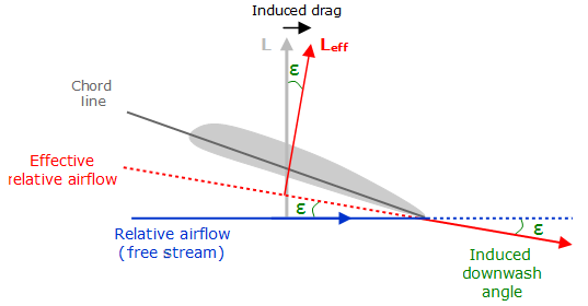
The vortices reduce the wing's ability to generate lift, so that it requires a higher angle of attack for the same lift, which tilts the total aerodynamic force rearwards and increases the drag component of that force. The angular deflection is small and has little effect on the lift. However, there is an increase in the drag equal to the product of the lift force and the angle through which it is deflected. Since the deflection is itself a function of the lift, the additional drag is proportional to the square of the lift.[3]: Section 5.17 The resulting vortices change the speed and direction of the airflow behind the trailing edge, deflecting it downwards, and thus inducing downwash behind the wing.[citation needed]
The vortices created are unstable,[clarification needed] and they quickly combine to produce wingtip vortices which trail behind the wingtip.[3]: Section 5.14
Calculation of induced drag
For a planar wing with an elliptical lift distribution, induced drag Di can be calculated as follows:
- ,
where
- is the lift,
- is the standard density of air at sea level,
- is the equivalent airspeed,
- is the ratio of circumference to diameter of a circle, and
- is the wingspan.
From this equation it is clear that the induced drag decreases with flight speed and with wingspan. Deviation from the non-planar wing with elliptical lift distribution are taken into account by dividing the induced drag by the span efficiency factor .
To compare with other sources of drag, it can be convenient to express this equation in terms of lift and drag coefficients:[9]
- , where
and
- is the aspect ratio,
- is a reference wing area.
This indicates how, for a given wing area, high aspect ratio wings are beneficial to flight efficiency. With being a function of angle of attack, induced drag increases as the angle of attack increases.[3]: Section 5.17
The above equation can be derived using Prandtl's lifting-line theory.[citation needed] Similar methods can also be used to compute the minimum induced drag for non-planar wings or for arbitrary lift distributions.[citation needed]
Reducing induced drag
For a typical twin-engine wide-body aircraft at cruise speed, induced drag is the second-largest component of total drag, accounting for approximately 37% of total drag. Skin friction drag is the largest component of total drag, at almost 48%.[10][11][12]: 20 Reducing induced drag can therefore significantly reduce cost and environmental impact.[12]: 18
According to the equations above, for wings generating the same lift, the induced drag is inversely proportional to the square of the wingspan. A wing of infinite span and uniform airfoil segment (or a 2D wing) would experience no induced drag,[13] The drag characteristics of a wing with infinite span can be simulated using an airfoil segment the width of a wind tunnel.[14] A two-dimensional wing can still reduce drag for a given lift, by travelling faster and reducing its angle of attack, therefore reducing profile drag.[15]
An increase in wingspan or a solution with a similar effect is only way to reduce induced drag.[5]: 4.10 Some early aircraft had fins mounted on the tips. More recent aircraft have wingtip-mounted winglets to reduce the induced drag.[16] Winglets also provide some benefit by increasing the vertical height of the wing system.[5]: 4.10 Wingtip mounted fuel tanks and wing washout may also provide some benefit.[citation needed]
Typically, the elliptical spanload (spanwise distribution of lift) produces the minimum induced drag[17] for planar wings. A small number of aircraft have a planform approaching the elliptical — the most famous examples being the World War II Spitfire and Thunderbolt. Tapered wings with straight leading edges can also approximate an elliptical lift distribution. For modern wings with winglets, the ideal spanload is not elliptical.[5]: 4.9
For a given wing area, a high aspect ratio wing will produce less induced drag than a wing of low aspect ratio.[18] While induced drag is inversely proportional to the square of the wingspan, not necessarily inversely proportional to aspect ratio, if the wing area is held constant, then induced drag will be inversely proportional to aspect ratio. However, since wingspan can be increased while decreasing aspect ratio, or vice versa, the apparent relationship between aspect ratio and induced drag does not always hold.[19]
Combined effect with other drag sources

In 1891, Samuel Langley published the results of his experiments showing higher aspect ratio flat plates had higher lift and lower drag.[1] He also observed that travelling at higher speeds used less power, [20] however his experiments had only been carried out at relatively low speeds.[21] At higher speeds, parasitic drag comes to dominate, and power required increases.
Induced drag must be added to the parasitic drag to find the total drag. Since induced drag is inversely proportional to the square of the airspeed (at a given lift) whereas parasitic drag is proportional to the square of the airspeed, the combined overall drag curve shows a minimum at some airspeed - the minimum drag speed (VMD). An aircraft flying at this speed is operating at its optimal aerodynamic efficiency. According to the above equations, the speed for minimum drag occurs at the speed where the induced drag is equal to the parasitic drag.[3]: Section 5.25 This is the speed at which for unpowered aircraft, optimum glide angle is achieved. This is also the speed for greatest range (although VMD will decrease as the plane consumes fuel and becomes lighter). The speed for greatest range (i.e. distance travelled) is the speed at which a straight line from the origin is tangent to the fuel flow rate curve.
The curve of range versus airspeed is normally very shallow and it is customary to operate at the speed for 99% best range since this gives 3-5% greater speed for only 1% less range. Flying higher where the air is thinner will raise the speed at which minimum drag occurs, and so permits a faster voyage for the same amount of fuel. If the plane is flying at the maximum permissible speed, then there is an altitude at which the air density will be sufficient to keep it aloft while flying at the angle of attack that minimizes the drag. The optimum altitude will increase during the flight as the plane becomes lighter.
The speed for maximum endurance (i.e. time in the air) is the speed for minimum fuel flow rate, and is always less than the speed for greatest range. The fuel flow rate is calculated as the product of the power required and the engine specific fuel consumption (fuel flow rate per unit of power[a]). The power required is equal to the drag times the speed.
See also
Notes
- ^ The engine specific fuel consumption is normally expressed in units of fuel flow rate per unit of thrust or per unit of power depending on whether the engine output is measured in thrust, as for a jet engine, or shaft horsepower, as for a propeller engine. To convert fuel rate per unit thrust to fuel rate per unit power one must divide by the speed.
References
- ^ a b c Bjorn Fehrm (Nov 3, 2017). "Bjorn's Corner: Aircraft drag reduction, Part 3". Leeham.
- ^ Hurt, H. H. (1965) Aerodynamics for Naval Aviators, Figure 1.30, NAVWEPS 00-80T-80
- ^ a b c d e f Clancy, L.J. (1975) Aerodynamics. Pitman Publishing Limited, London. ISBN 0-273-01120-0
- ^ Kermode, A.C. (1972). Mechanics of Flight, Figure 3.29, Ninth edition. Longman Scientific & Technical, England. ISBN 0-582-42254-X
- ^ a b c d e f McLean, Doug (2005). Wingtip Devices: What They Do and How They Do It (PDF). 2005 Boeing Performance and Flight Operations Engineering Conference.
- ^ Anderson, John D., Jr. (2017). Fundamentals of aerodynamics (Sixth ed.). New York, NY: McGraw-Hill Education. p. 20. ISBN 978-1-259-12991-9.
{{cite book}}: CS1 maint: multiple names: authors list (link) - ^ Abbott, Ira H., and Von Doenhoff, Albert E., Theory of Wing Sections, Section 1.2 and Appendix IV
- ^ a b McLean, Doug (2012). Understanding Aerodynamics: Arguing from the Real Physics. ISBN 978-1119967514.
- ^ Anderson, John D. (2005), Introduction to Flight, McGraw-Hill. ISBN 0-07-123818-2. p318
- ^ Robert, JP. Cousteix, J (ed.). "Drag reduction: an industrial challenge". Special Course on Skin Friction Drag Reduction. AGARD Report 786. AGARD: 2-13.
- ^ Coustols, Eric (1996). Meier, GEA; Schnerr, GH (eds.). "Control of Turbulent Flows for Skin Friction Drag Reduction". Control of Flow Instabilities and Unsteady Flows: 156. ISBN 9783709126882. Retrieved 24 March 2022.
- ^ a b Marec, J.-P. (2001). Peter Thiede (ed.). "Drag Reduction: a Major Task for Research". Aerodynamic Drag Reduction Technologies. Springer: 17–27. Bibcode:2001adrt.conf...17M. doi:10.1007/978-3-540-45359-8_3. ISBN 978-3-642-07541-4. ISSN 0179-9614. Retrieved 22 March 2022.
- ^ Houghton, E. L. (2012). "1.6". Aerodynamics for engineering students (Sixth ed.). Waltham, MA. p. 61. ISBN 978-0-08-096632-8.
For a two-dimensional wing at low Mach numbers, the drag contains no induced or wave drag
{{cite book}}: CS1 maint: location missing publisher (link) - ^ Molland, Anthony F. (2007). "Physics of control surface operation". Marine rudders and control surfaces : principles, data, design and applications (1st ed.). Amsterdam: Elsevier/Butterworth-Heinemann. p. 41. ISBN 9780750669443.
With infinite span, fluid motion is 2-D and in the direction of flow perpendicular to the span. Infinite span can, for example, be simulated using a foil completely spanning a wind tunnel.
- ^ "Inclination Effects on Drag". www.grc.nasa.gov. Retrieved 22 April 2022.
- ^ Richard T. Whitcomb (July 1976). A design approach and selected wind-tunnel results at high subsonic speeds for wing-tip mounted winglets (PDF) (Technical report). NASA. 19760019075. p. 1:
Winglets, which are small, nearly vertical, winglike surfaces mounted at the tips of a wing, are intended to provide, for lifting conditions and subsonic Mach numbers, reductions in drag coefficient greater than those achieved by a simple wing-tip extension with the same structural weight penalty.
{{cite tech report}}: CS1 maint: date and year (link) - ^ Glauert, H. The Elements of Aerofoil and Airscrew Theory (1926); referenced in Fig. 5.4 of Airplane Aerodynamics by Daniel O. Dommasch, Sydney S. Sherby, Thomas F. Connolly, 3rd ed. (1961)
- ^ "Induced Drag". Retrieved 5 May 2015.
- ^ Illsley, Michael. "Why Aspect Ratio doesn't Matter – Understanding Aerospace". Understanding Aerospace. Retrieved 25 March 2022.
- ^ Hansen, James R. (2004). The Bird Is on the Wing: Aerodynamics and the Progress of the American Airplane. College Station: Texas A&M University Press. p. 23. ISBN 978-1-58544-243-0. Retrieved 13 April 2022.
- ^ Hallion, Richard (8 May 2003). Taking Flight: Inventing the Aerial Age, from Antiquity Through the First World War. Oxford University Press, USA. p. 147. ISBN 978-0-19-516035-2. Retrieved 13 April 2022.
Bibliography
- L. J. Clancy (1975), Aerodynamics, Pitman Publishing Limited, London. ISBN 0-273-01120-0
- Abbott, Ira H., and Von Doenhoff, Albert E. (1959), Theory of Wing Sections, Dover Publications, Standard Book Number 486-60586-8
- Luciano Demasi, Antonio Dipace, Giovanni Monegato, and Rauno Cavallaro. Invariant Formulation for the Minimum Induced Drag Conditions of Nonplanar Wing Systems, AIAA Journal, Vol. 52, No. 10 (2014), pp. 2223–2240. doi: 10.2514/1.J052837